| Your Cart |
0 items - $0.00 |
Check Out |
NO. Do not exceed a torque of 15 ft-lb or screw the fittings tighter than two full turns past hand tight, whichever happens first.
Fittings:
• #4 AN816-4 Steel
• #6 AN816-6 Steel
• #8 AN816-7 Steel (JPI only has -7)
** Do Not Use Aluminum or Brass – only Steel **
** Do not use Teflon tape or thread sealent compound of any kind – this will void transducer warranty.** [ See “Report #503 Rev B: Date 03/14/97 under heading #2 “Initial Check Out” – line item #14. ]
Set the main tank size to 65 gallons and the Aux tank size to 10 gallons. Then at startup will be asked about both
Yes
300 – 360 HP Radial -> use the #231. These aircraft DO NOT USE THE #201 .The reason is: Although the model #201 and #231 both have 1/4″ NPT ports and resemble each other externally, on the ‘INLET’ side the #231 has a larger ‘INLET’ internal orifice I.D. than the #201. Less back pressure.
Over 400 HP Radial -> use the Hi Flow Tranducer(FT 4-8AEXS-LEA-2029)
NO RADIALS SHOULD USE THE #201 TRANSDUCER
Call JPI Sales at 800-345-4574
Make sure the transducer is Horizontal with the three wires up. Failure to do this will result in premature failure. Please refer to Report #503 that came with your EDM with Fuel Flow.
Mount in a horizontal position with the wires up, as this ensures that the rotor is in proper orientation to the flow of fuel just as it was calibrated.
Be sure there is no bend in the line closer than 6 inches before or after the transducer. Do not use aluminum fittings when installing the fuel flow transducer.
For carbureted engines, before the carburetor. If the transducer is higher than the carburetor, put an anti-siphon loop in the line that peaks higher than the transducer (see installation manual, but the diagram shows the transducer on its side, rather than the correct position which is with the wires coming off the top).
For injected engines, between the engine fuel pump and the servo regulator. For injected engines with vapor return lines (rare), between the servo regulator and the flow divider (spider).
Mounting the transducer between the electric boost pump and the mechanical pump is not recommended.
Do not hard mount the transducer to the engine. Vibration may damage the internal parts of the transducer or cause erratic readings.
Tighten fittings not more than 15 ft lb = 180 in lbs., or two full turns past hand tight.
** Do not use Teflon tape or thread sealent compound of any kind – this will void transducer warranty.** [ See “Report #503 Rev B: Date 03/14/97 under heading #2 “Initial Check Out” – line item #14. ]
Since the transducer body is aluminum, you must use steel fittings on the transducer and use not more than 15 ft lb = 180 in lbs., or two full turns past hand tight.
** Do not use teflon tape, or thread sealant compound of any kind. [ See #503 Fuel Flow Installation Manual – Heading #2 “Initial Check Out” — line item #14.]
Fittings:
• #4 AN816-4 Steel 1/4 NPT
• #6 AN816-6 Steel 1/4 NPT
• #8 AN816-7 Steel (JPI only has -7 1/4 NPT)
** Do Not Use Aluminum or Brass – only Steel ***
The Power, which is 12 volts regulated, is supplied by the EDM.
The transducer is marked IN and OUT. Make sure this is correct. It is probably installed backwards. Also check the K factor marked on the side of the transducer. If the instrument came from JPI, see invoice for K factor.
2.) Check that the transducer harness wiring is not routed with or adjacent to ignition wires, alternator wires, spark plug leads, or cabin heater ignition wires. Also check connections and crimps.
1.) Check for air entering system at selector valve (change o-ring) or elsewhere. ** The next time the aircraft is flown in cruise, turn on the boost pump for one minute. If the fuel flow drops, then this is an indication that air is leaking into the fuel line upstream of the transducer. It is possible that air is leaking into the system through the seal valve or other connection. Fuel stain may not be visible.
2.) K-factor may not be set correctly. The 201B transducer will have a K-factor of ~29. The 231 will be ~19. Hoskins or Shadin transducers will be ~84. **The lower the K factor the higher the Fuel Flow reading (Flow per hour) the HIGHER the K factor the LOWER the Fuel Flow reading.
No. The JPI electrical system is not noise sensitive like the Shadin system.
The following do NOT need a transducer because a digital transducer is already installed:
F33A serial numbers >= CE-919,
F33C >= CU-156,
V35B >= D-10354,
A36 >= E-1766,
A36TC >= EA-159,
B36TC all.
If the aircraft already has a three(3) wire type digital transducer, then the FF JPI can piggy back off that existing transducer. If this transducer is getting its power from another gage, then you would cap off the ‘red’ wire on the JPI FF harness and just use the ‘white'(signal) and ‘black'(ground) wires. Program the correct K factor into the JPI. (Shadin, Hoskins, Beech, and Piper have K factors of 84.00 to 85.00)
A.) Change the alarm limits to CARB? Y:
EDM may have the K factor too low. The correct factor is around 19.xx for a #231; 29.xx for JPI #201, and 84.00/85.00 (Hoskins and Shadin)
1.) Be sure fuel units are correct: Gal, Pounds, Liters or Kgs.
2.) K-factor may not be set correctly. The 201B transducer will have a K-factor of ~29. The 231 will be ~19. Hoskins or Shadin transducers will be ~84. **The lower the K factor the higher the Fuel Flow reading (Flow per hour) the HIGHER the K factor the LOWER the Fuel Flow reading.
3.) Check for air entering system at selector valve (change o-ring) or elsewhere. ** The next time the aircraft is flown in cruise, turn on the boost pump for one minute. If the fuel flow drops, then this is an indication that air is leaking into the fuel line upstream of the transducer. It is possible that air is leaking into the system through the seal valve or other connection. Fuel stain may not be visible.
4.) Make sure there are no 90-degree fittings within 4” of the inlet/outlet side of the transducer. Cavitations in the transducer will result in inaccurate readings. A swirl in the flow stream caused by improper line geometry may cause the rotor to have an artificially high frequency
5.) Check that the wiring is not adjacent to ignition or power wires. Shield the signal wire if necessary.
Check EGT-ALL-FF switch setting (and connections).
• Check connections/crimps between instrument and fuel flow transducer. With the transducer unplugged from the FF harness, you should see around 12v +/- on the ‘red’ wire and 5v on the ‘white’ signal wire. If you do not see these voltages on the FF harness, then varify by taking these voltages off the EDM Fuel Flow pigtail itself. (Refer to your instruments install manual for pin#’s.) You may have a faulty harness. If you do not see these voltages off the instrument itself, then send in for repair. Call for RMA number before sending.
• Check with Fuel Flow Tester to verify that the instrument is working and the transducer connector is getting power and ground. This tester can be purchase at JPI for $35.00. Call the Sales Department at: 800-345-4574.
No. EDM-700 must be returned to factory modification. Please call for pricing and a RMA number before shipping in for upgrade.
The #201:
Accuracy: – +/- 1 gallon per 100.
Pressure drop: 1.2 psi at 30 GPH, 4.8 psi at 50 GPH
Range: 0.6 to 50 GPH [ For fuel injected or engines with engine driven fuel pumps.]
The #231:
Accuracy: 2%;
Pressure drop: 0.31 psi at 30 GPH, 2.8 psi at 60 GPH
Range: 3 to 90 GPH [ For ‘gravity’ fuel systems, which means NO engine driven fuel pumps. Also for radial engines with a 300 to 360 HP rating. These aircraft DO NOT USE THE #201 .The reason is: Although the model #201 and #231 both have 1/4″ NPT ports and resemble each other externally, on the ‘INLET’ side each transducer model has a different internal orifice size. The #231 has a larger ‘INLET’ internal orifice I.D. than the #201. Less back pressure.]
**** See #231 image below. Note ‘yellow’ wire cap. ****
** Do not use Teflon tape or thread sealent compound of any kind – this will void transducer warranty.** [ See “Report #503 Rev B: Date 03/14/97 under heading #2 “Initial Check Out” – line item #14. ]
The FXT-201: Standard transducer used on every IO(fuel injected) engine, and carbureted engine with a mechanical fuel pump.
The FXT-231: Used on Carbureted engines without a Mechanical Fuel pump. (gravity feed aircraft)
On high HP Radial engines:
300 – 360 HP Radial -> use the #231
Over 400 HP Radial -> use the Hi Flow Tranducer(FT 4-8AEXS-LEA-2029)
** ATTN: RADIALS SHOULD NOT USE THE #201 **
Never pass high pressure air through or blow through the transducer, damage will occur.
Range (201) 0.6 to 60 GPH, (231) 3 to 90 GPH, (H) 3 to 120 GPH
K-factor (201) ~ 29.00, (231) ~19.50, (H) ~48.00
Linearity 1%
Pressure drop (201) 1.2 psi at 30 GPH, 4.8 psi at 60 GPH
Pressure drop (231) 0.31 psi at 30 GPH, 2.8 psi at 60 GPH
Pressure drop (H) 0.23 psi at 30 GPH, 0.8 psi at 60 GPH
Working pressure (201, 231) 200 psi, (H) 1500 psi
Maximum burst pressure 2000 psi
Temperature range, operating -55°C to 70°C
Temperature range, non-operating (201, 231) -65°C to 125°C, (H) -65°C to 100°C
Fuel ports (201, 231) 1/4 Female NPT (H) AN816-8-8
** Do not use Teflon tape or thread sealent compound of any kind – this will void transducer warranty.** [ See “Report #503 Rev B: Date 03/14/97 under heading #2 “Initial Check Out” – line item #14. ]
Be sure fuel units are correct: Gal, Pounds, Liters or Kgs …
1. Go to set alarm limits (Both buttons…END Y…both buttons).
2. Step to FUEL FLW…FUEL GAL.
3. Tap LF to display FUEL KGS…FUEL LTR…FUEL LBS.
4. Tap STEP repeatedly to END Y.
EDM-700 may not be in accumulate mode and one or more fuelings have taken place. Or the K factor may be wrong.
Adjust the K-factor …
1. Go to pilot program mode (Hold both buttons to see PROGRAM).
2.Tap STEP until you see KF-SET… 29.00=KF
3. Hold both buttons until the first digit flashes.
4. Hold or tap LF to set the first digit.
5. Tap STEP to move to the next digit.
6. Hold both buttons to exit.
NO. Our 201 Flowscan tranducers are in the 29.00 range and 84.00 to 85.00.
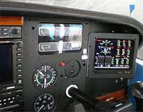
EDM-700 and EDM-800 Fuel Flow pin assignments
1, RS-232 out
2, RS-232 in
4, wht FF signal (pin 1 on transducer connector)
5, red FF power (pin 3 on transducer connector)
6, blk FF return (pin 3 on transducer connector)
7, Switch com
8, Switch EGT
9, Switch FF
11, Remote FF alarm
EDM-760:
#1 – RS-232 out to GPS
#2 – RS-232 in from GPS
#3 -‘GND’ (Not used.)
#4 – FFLF ‘left’ signal – 0-5v square wave. (White)
#5 – FFLF & FFRF – power +12v -‘Y’ Connector (red)
#6 – FFLF & FFRF – ground -‘Y’ Connector (black)
#7 – Switch ‘com’- (“ALL”)
#8 – Switch – (“EGT”)
#9 – Switch – (“FF”)
#11 – Remote alarm light (Sinks to ground.)
#12 – FF ‘right’ signal 0-5 square wave. (White)
Fuel Flow Tester Instructions
|
Symptom
|
Problem
|
|
Red LED indicator on fuel flow tester does not light.
|
Check the fuel flow cable for continuity from the instrument to the transducer end.
FS-450: 12 volts between pins 5 and 3 on FF connector.
EDM-700: 12 volts between pins 5 and 6 on FF connector.
EDM-760: 12 volts between pins 5 and 6 on FF connector.
EDM-900/930/1000C: 12 volts between pins 5 and 6 on theP4 FF connector.
|
|
The FS-450 or EDM displays a positive rate of fuel flow with the fuel flow tester, but not with the fuel flow transducer.
If the K-factor is approximately 19,000 (19.00=KF), the correct rate shown on the display should be between 18 and 20 GPH.
If the K-factor is approximately 29,000 (29.00=KF), the correct rate shown on the display should be between 12 and 14 GPH.
|
If the reading on the display is in the correct rate range, then the fuel flow transducer is most likely defective. Return for repair or replacement. The instrument is okay.
**If some other K-factor transducer is used, the display should read approximately the value resulting from dividing 360 by the K-factor. For example: 360/85.00 = 4.2 displayed.
|
|
The FS-450 or EDM displays a zero or erroneous rate of fuel flow with the fuel flow tester as well as with the fuel flow transducer.
|
Check that the K-factor is correct. If it is, the instrument is most likely defective. Return the instrument only—not the transducer—to the factory for repair.
|
JPI 201 K-factor = about 29.xx – 30.xx
JPI 231 K-factor = about 19.xx – 20.xx
Beech K-factor = about 85.00 – (3 wire) * Our FS-450’s and EDM’s hook up to only 3-wire type transducers only.
Piper K-factor = 84.00 to 85.00 -(3 wire) * Our FS-450’s and EDM’s hook up to only 3-wire type transducers only.
Hoskins K-factor = 84.00 to 85.00 -(3 wire) * Our FS-450’s and EDM’s hook up to only 3-wire type transducers only.
Set the approximate value and then fine tune using procedure in the pilot’s guide.
FOR THE EDM-700/800 ——— #700709
FOR THE EDM-760 ————— #700709T
NO. IF this Bendix uses a ‘spring-restrained vane’, within the metering chamber, it will not work.
Use a pull-up resister (1k) and LED between the red and white wires. With the transducer plugged into the FF harness of the FS-450 or EDM, connect the 1K resistor at the White wire of the transducer – transducer side. The other end of the resistor is connected to a LED. The other lead of the LED is now connected to the red wire of the transducer. Now when fuel is passed through the transducer, you should see the LED flickering. Again the transducer must be plugged into the FF harness of the FS-450 or EDM and these instruments need to be powered on.
A Fuel Flow Tester(see below) is also available for $35.00. This will test your FS-450 or EDM. If these test OK, then by deduction the transducer is faulty. You can purchase a Fuel Flow tester by calling JPI direct (800) 345-4574 (please ask for the Sales Department).

